Français
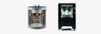
Technical Ceramics - FFF vs PAM
Produce with industrial quality material at unbeatable cost.
Pollen AM develops its range of industrial technical ceramics and presents the latest results obtained with a 96% alumina feedstock produced by one of the European leaders, Inmatec Technologies GmbH.
The following parts were produced on a Pam Series MC system using a Ø 0.4 mm nozzle and a layer height of 0.15 mm. The debinding and sintering processes were carried out in partnership with Inmatec Technologies GmbH.
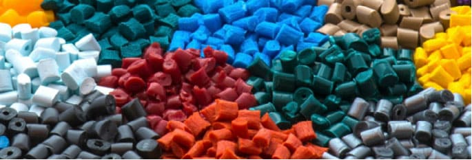
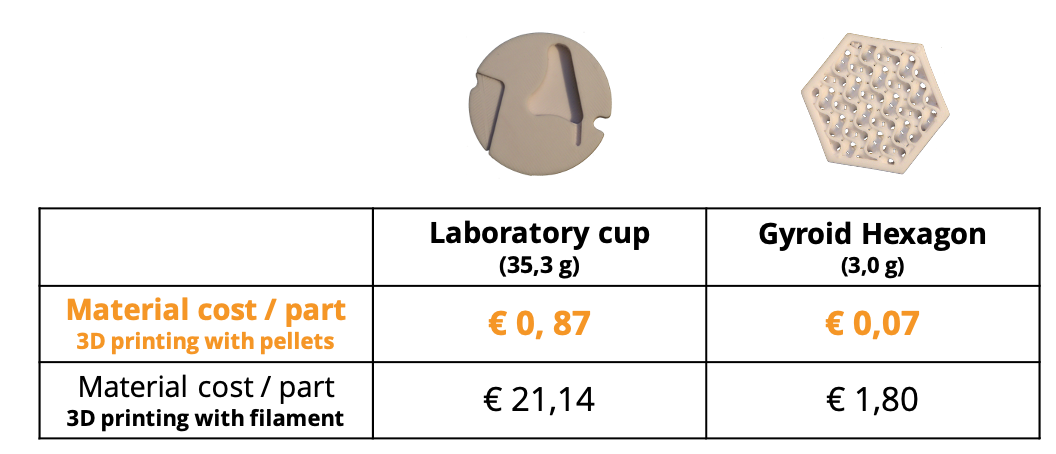
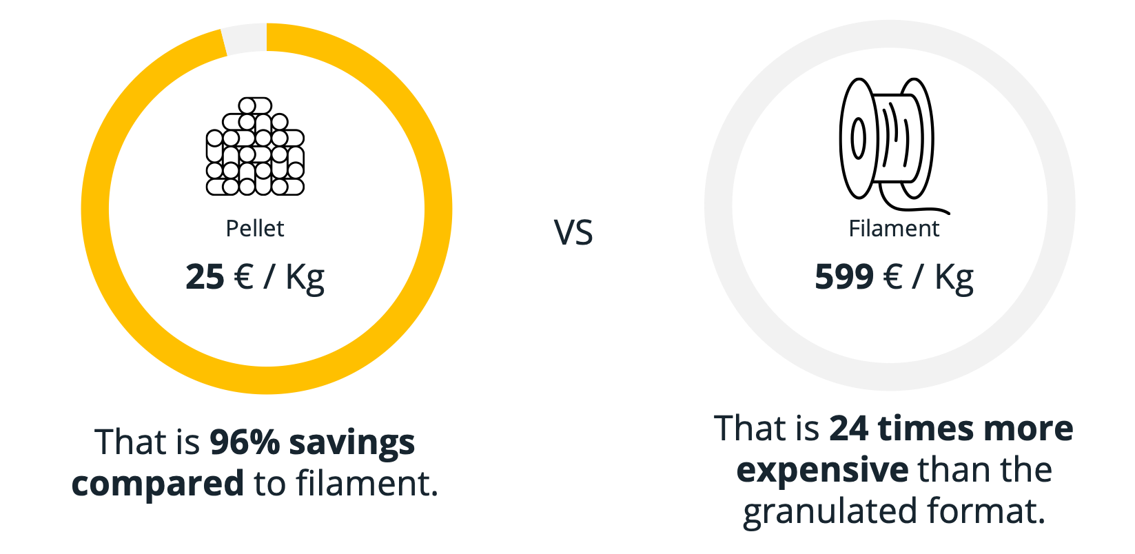
The use of ceramic feedstock in pellet form allows the Pam Series MC users to benefit from an adapted formulation to their projects at its lowest cost.
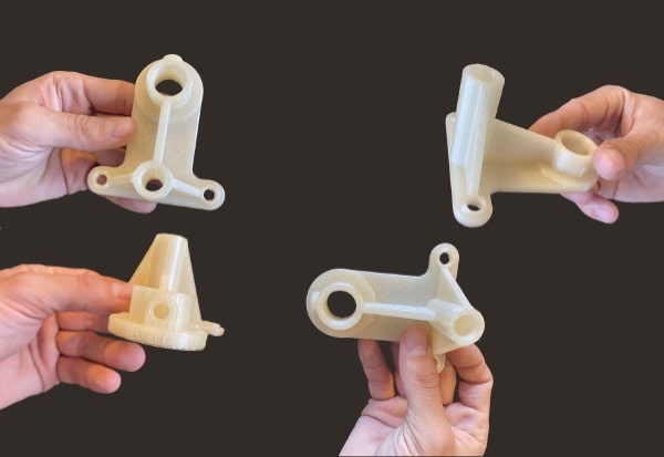
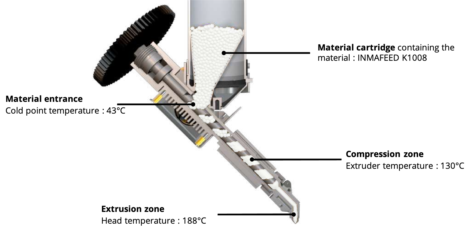
Process presentation
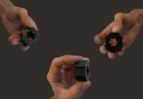
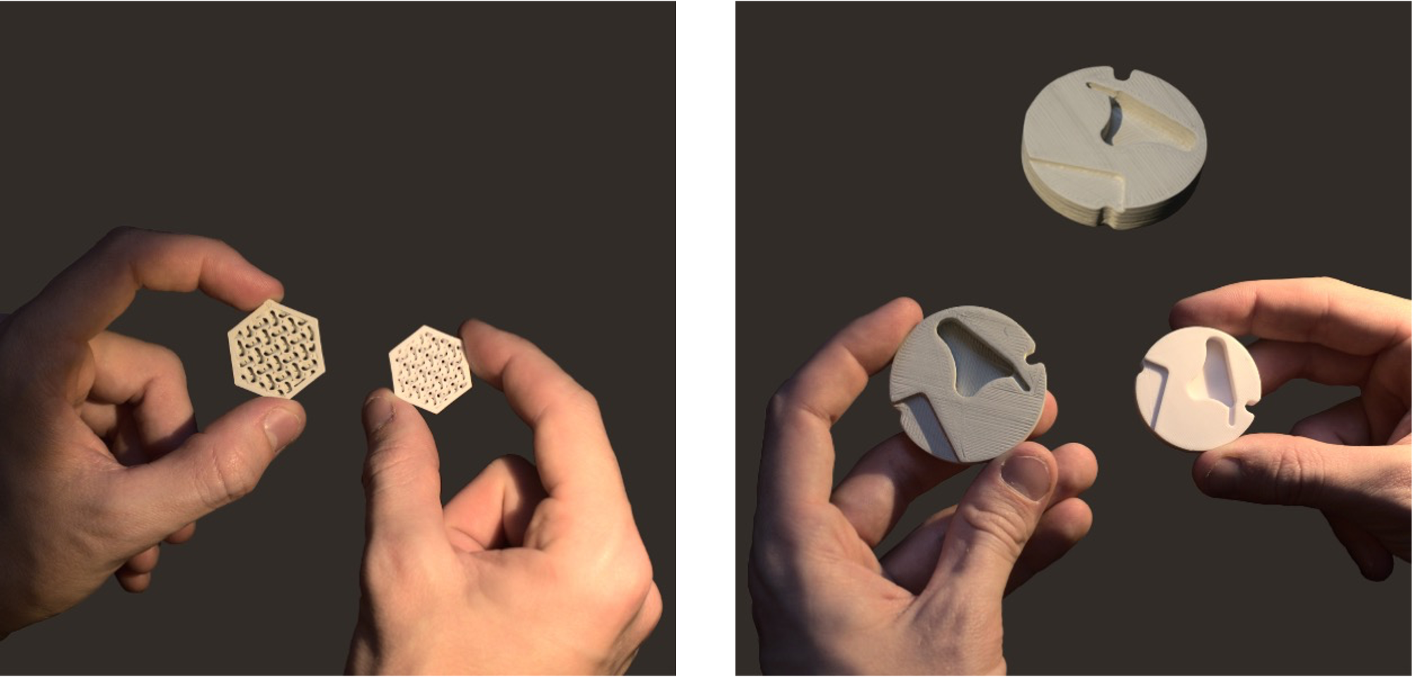
These two parts were 3D printed using INMATEC Technologies GmbH feedstock.
Feedstock presentation
The feedstock is based on an alumina powder (Al2O3, 96 %, KMS-96 BO (Martinswerk) and a thermoplastic binder system for the powder injection moulding process.
This material is an industrial CIM feedstock developed by INMATEC Technologies GmbH for injection moulding process.
Green parts need a binder removal in a two-step debinding process before being sintered. ( Discover the process)
First debinding step is dissolving the binder in a water bath.
In the second debinding step the remaining binder is thermally removed.
These general guidelines are based on the processing of test parts with a wall thickness of 5mm.
Material reference: INMAFEED K1008
Ceramic : Aliminium oxid (Al2O3, 96 %)
Powder supplier : Martinswerk
Powder reference : MARTOXID® KMS-96/BO
| Binder basis | Polyolefine based binder system. |
| Appearance | White to greyish pellets |
| Quality after sintering | Al2O3, 96 %, KMS-96 BO (Martinswerk) |
| Density | ± 3,8 g/cm3 |
| Shrinkage (approx.) | 15,5% |
Main 3D printing settings

Green part presentation
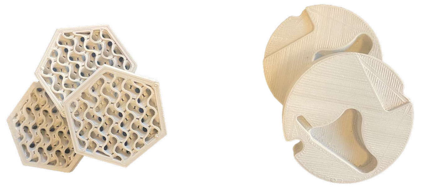
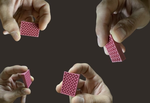
Hexagon with lattice structure : This part has been 3D printed with an internal porous structure.
Laboratory cup : This part has been 3D printed with a 100% infill density.
Debinding steps
Recommendations for the solvent de-binding (water bath)
It is recommended to debind the injected pieces in a circulating water bath at 30 °C.
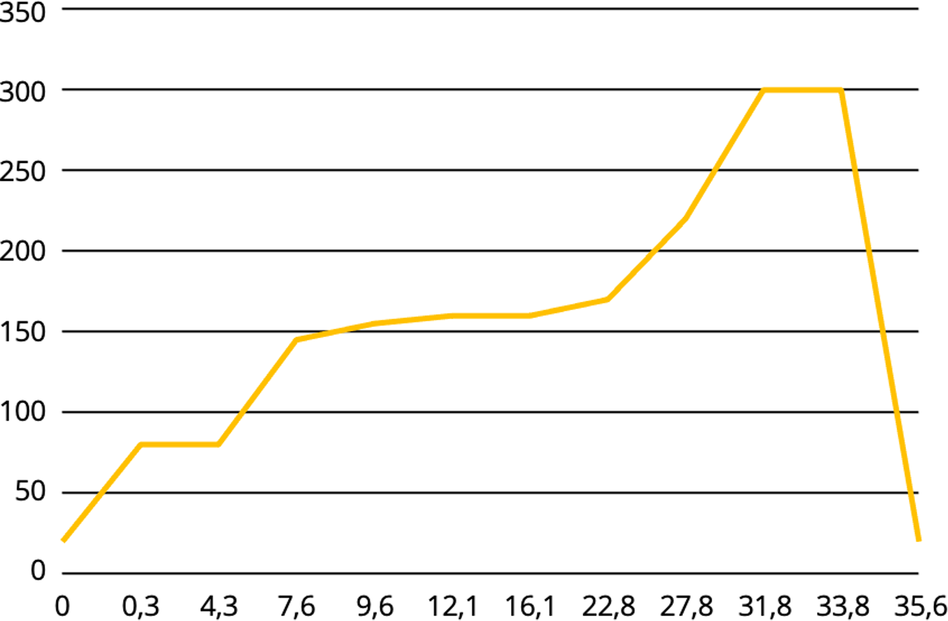
Recommendations for the thermal debinding
| Segment | From | To | Heating rate | Dwell time | Segment duration | Duration in total |
|---|---|---|---|---|---|---|
| 0 | 20°C | 0 h | 0 h | |||
| 1 | 20°C | 80°C | 180 K/h | 0,3h | 0,3 h | |
| 2 | 80°C | 80°C | 0 K/h | 4 h | 4 h | 4,3 h |
| 3 | 80°C | 145°C | 20 K/h | 3,3 h | 7,6 h | |
| 4 | 145°C | 155°C | 5 K/h | 2 h | 9,6 h | |
| 5 | 155°C | 160°C | 2 K/h | 2,5 h | 12,1 h | |
| 6 | 160°C | 160°C | 0 K/h | 4 h | 4 h | 16,1 h |
| 7 | 160°C | 170°C | 2 K/h | 6,7 h | 22,8 h | |
| 8 | 170°C | 220°C | 10 K/h | 5 h | 27,8 h | |
| 9 | 220°C | 300°C | 20 K/h | 4 h | 31,8 h | |
| 10 | 300°C | 300°C | 0 K/h | 2 h | 2 h | 33,8 h |
| 11 | 300°C | 20°C | 150 K/h | 1,9 h | 35,6 h |
Sintering steps
Recommendations for the Sintering (oxidic)

Sintering conditions may be adapted to part geometry and type of furnace
| Segment | From | To | Heating rate | Dwell time | Segment duration | Duration in total |
|---|---|---|---|---|---|---|
| 0 | 20°C | 0 h | 0 h | |||
| 1 | 20°C | 300°C | 130 K/h | 2,2h | 2,2 h | |
| 2 | 300°C | 300°C | 0 K/h | 1 h | 1 h | 3,2 h |
| 3 | 300°C | 1 500°C | 130 K/h | 9,2 h | 12,4 h | |
| 4 | 1 500°C | 1 620°C | 40 K/h | 2 h | 9,6 h | |
| 5 | 1 620°C | 1 620°C | 0 K/h | 1 h | 1 h | 16,4 h |
| 6 | 1 620°C | 900°C | 130 K/h | 5,5 h | 21,9 h | |
| 7 | 900°C | 25°C | 160 K/h | 5,5 h | 27,4 h |
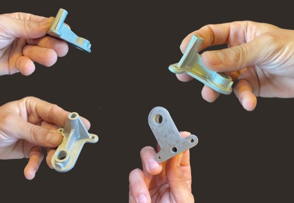
Sintered results
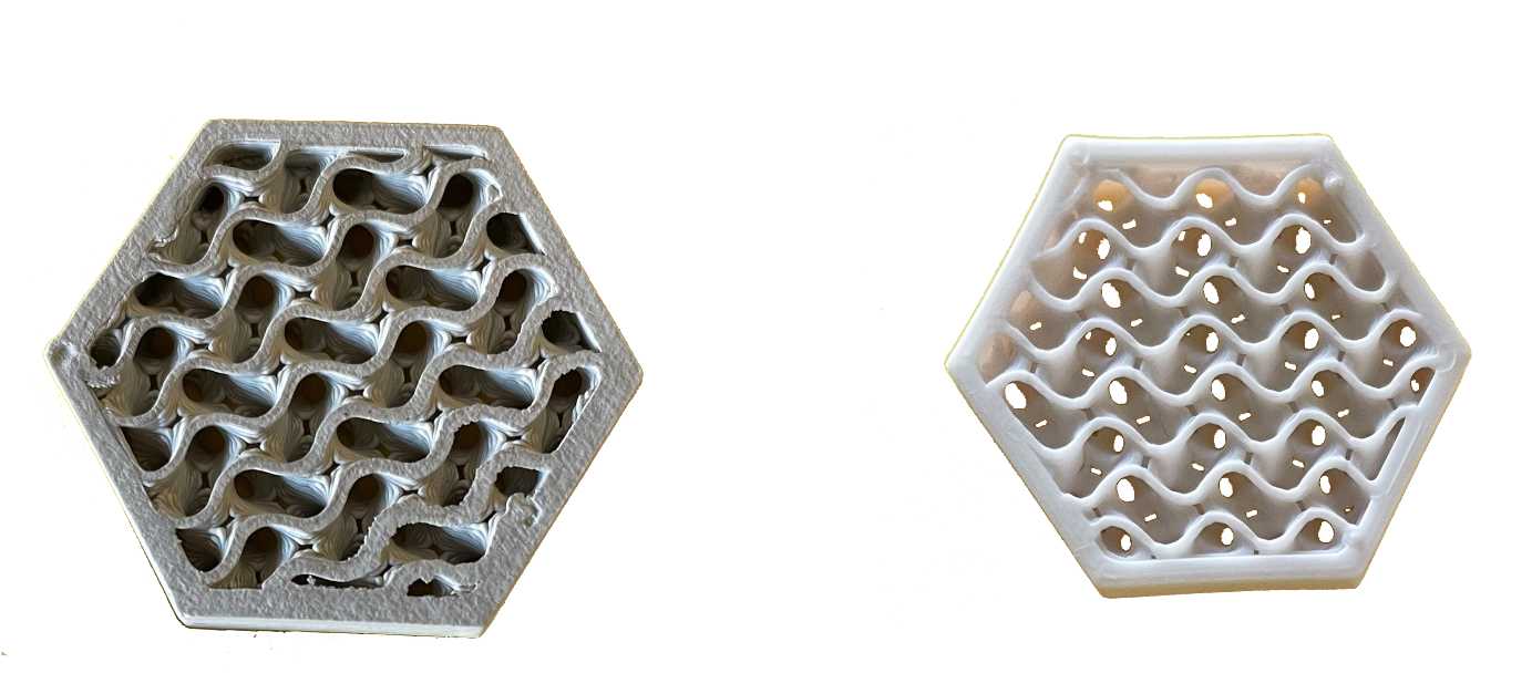
Left : Green part
Right : Sintered part.
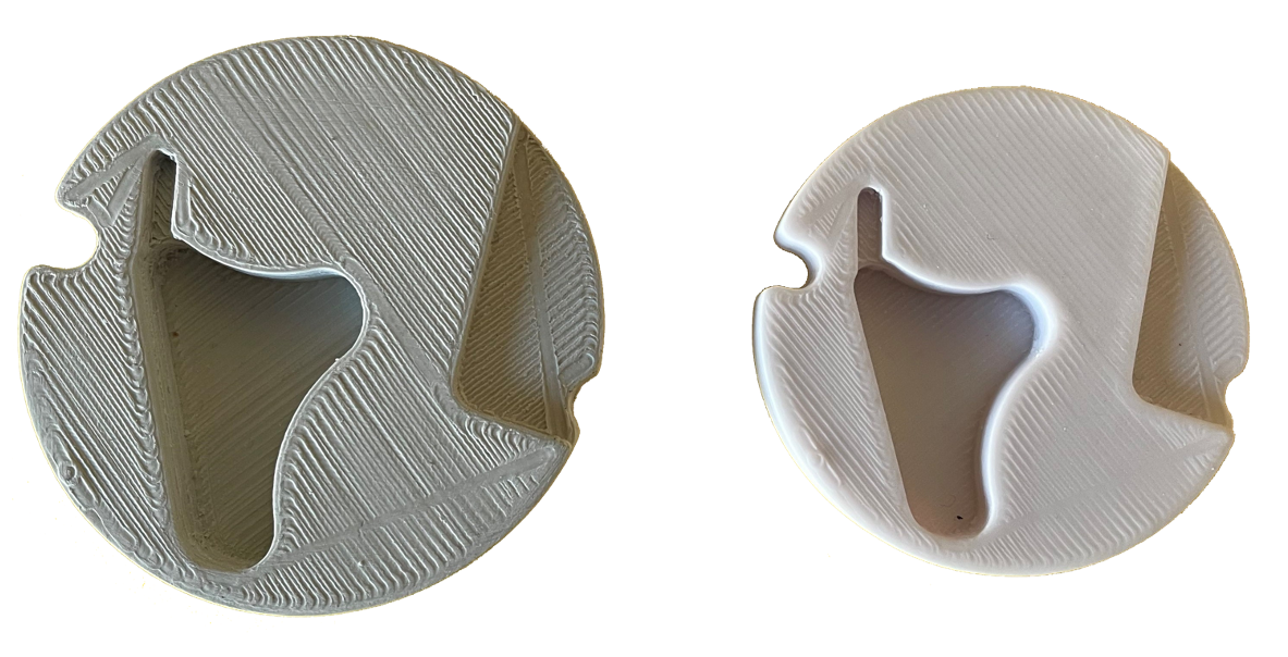
Left : Green part
Right : Sintered part.
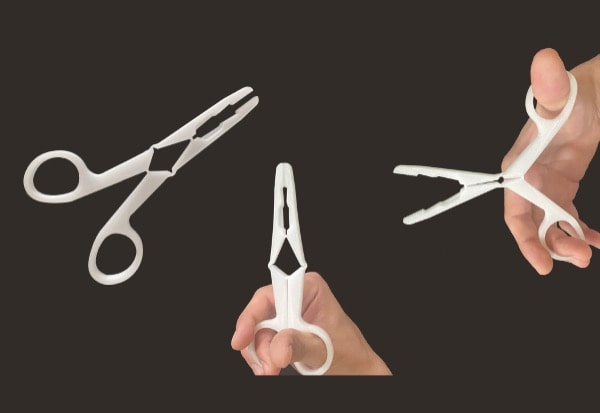
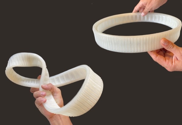
Let’s dive into the possibilities offered by PAM
From pellets to object, PAM technology offers the most direct process to high performances end-parts.
Metals Ceramics Commodity Elastomers Performance High Performance.