Infill
A crutial 3D printing parameter.
The printing of a part consists of two phases, the infill and the wall.
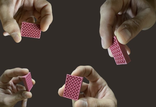
In 3D printing, Infill is the internal volume of the 3D parted part ; When slicing the 3D model, several types of infill are proposed.
It is thus possible to select a pattern but also a filling density. These choices must take into account the mechanical stress of the part and the strength/lightness ratio required.
If the mechanical strength of the part is insufficient, choose a mechanical adhesion
Infill is an important parameter that represents the fill rate of the part to be produced. This parameter is expressed as a percentage. An infill of 0% will allow the production of an empty part (Hollow), an infill of 20% means that the inside of the part will be composed of 20% material and 80% vacuum. An infill of 100% means that the part will be completely full.
In addition to the infill percentage, it is also possible to vary the infill geometries. Cura offers 13 different impacting infill geometries, production times and mechanical properties of the parts.
Synthesis of the rules for the first deposited layer
| Infill patern | Presentation |
|---|---|
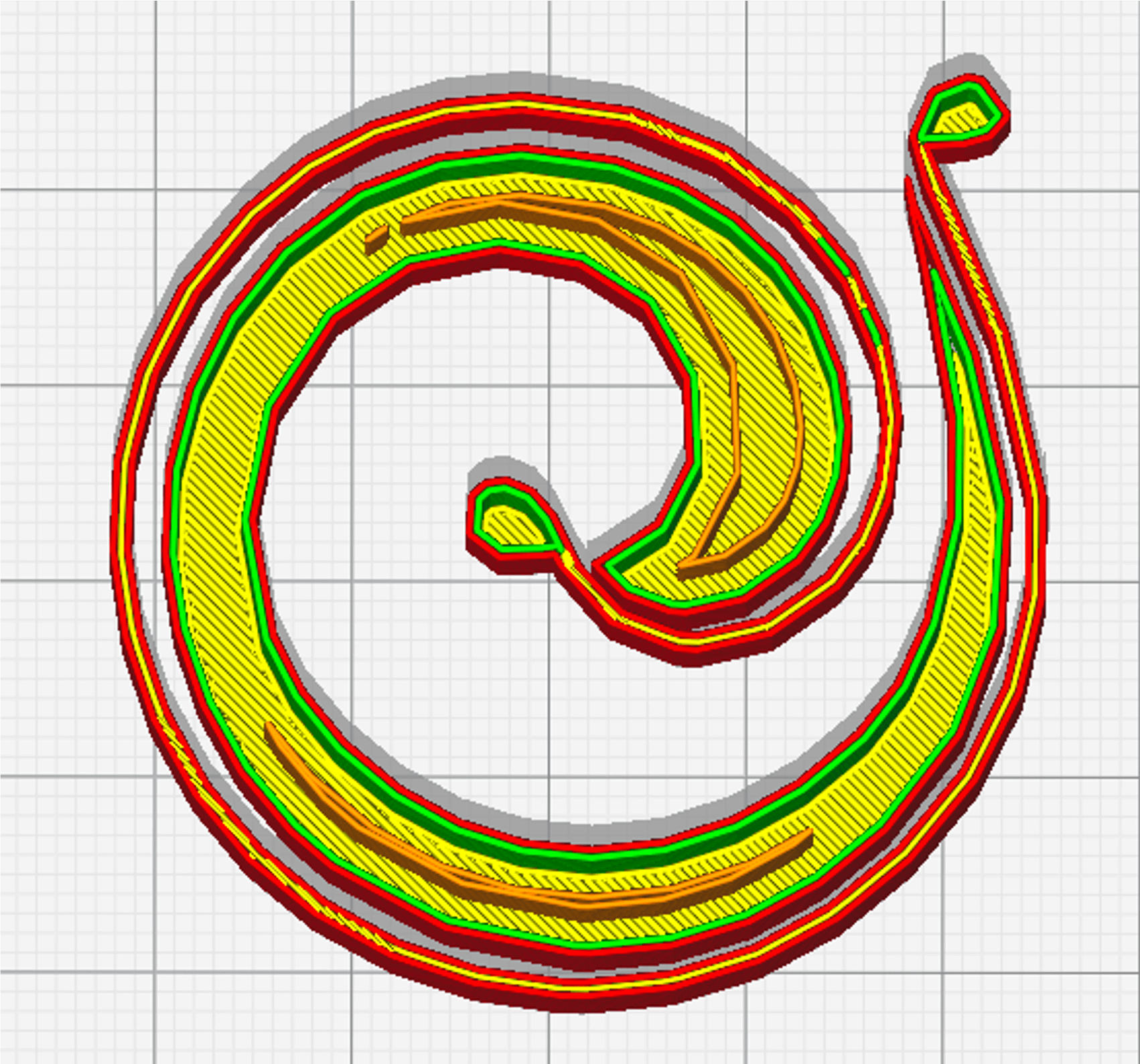 Concentric infill |
The concentric infill pattern is a 2D model consisting of producing concentric circles in the image of walls. The spacing between the concentric circles is a function of the chosen infill rate. The higher the infill rate, the smaller the space between the circles; conversely, the lower the infill rate, the larger the spacing between the circles. When printing so-called semi-flexible parts, it can be useful to use infill patterns that preserve the flexible nature of the material. Infill patterns such as Concentric, Cross and Cross 3D are so-called "flexible" printing patterns. Recommended infill percentages : 20 to 100 %. |
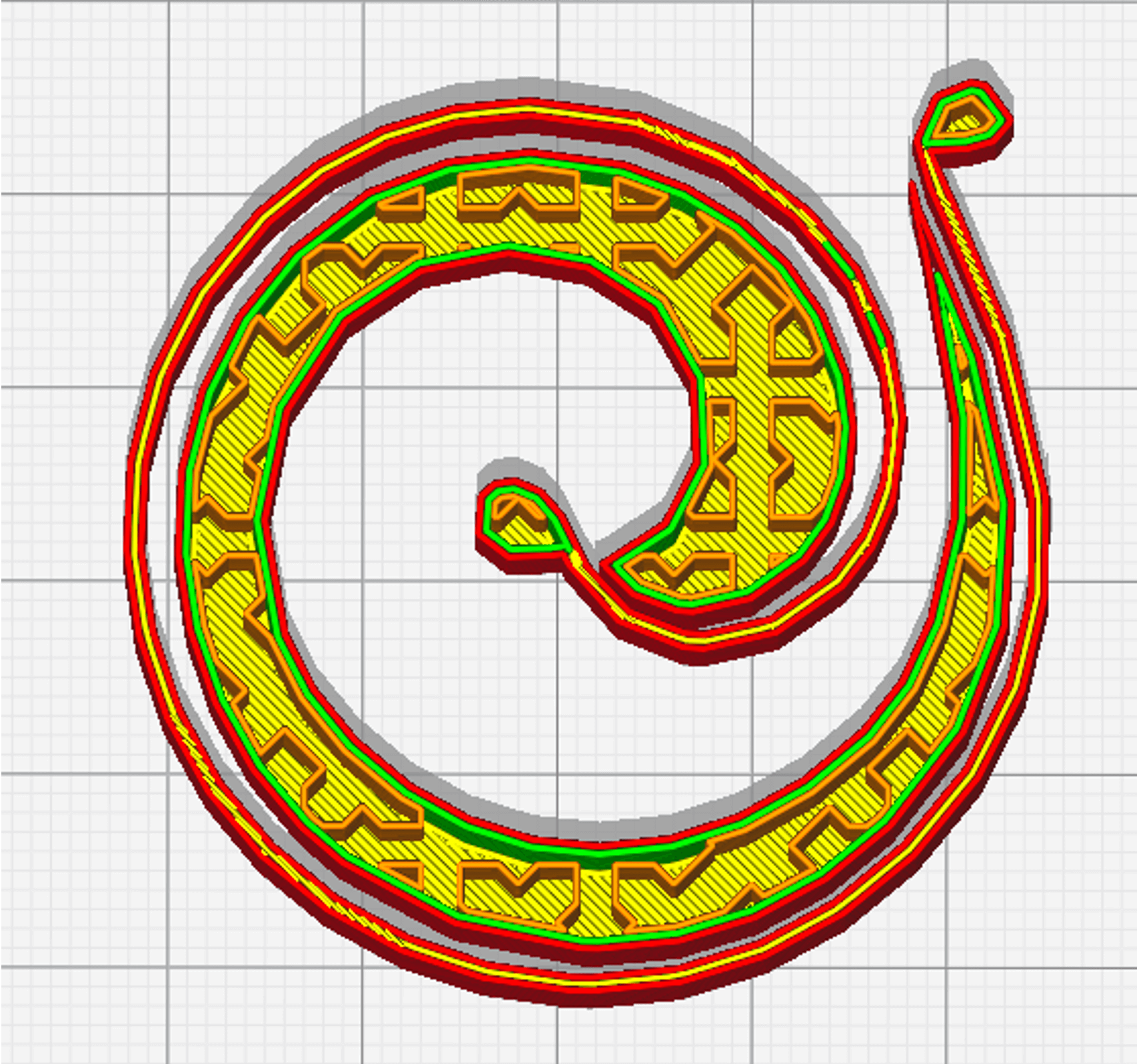
Cross Infill |
The Cross infill pattern is a 2D model producing "cross" shaped grids. The spaces between the crosses and the grids allow to obtain a more or less large flexibility. When printing so-called semi-flexible parts, it can be useful to use infill patterns that preserve the flexible nature of the material. Fill patterns such as Concentric, Cross and Cross 3D are so-called "flexible" printing patterns. Recommended infill percentages : 20 à 100 %. |
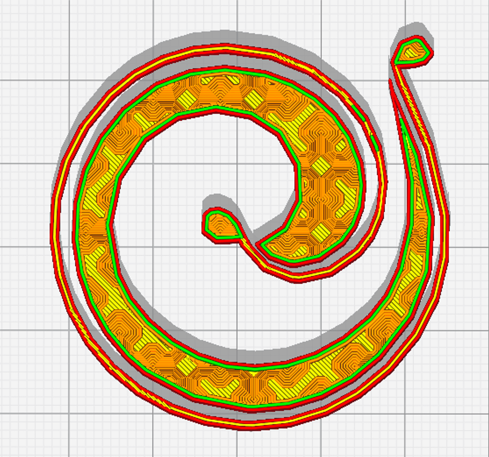 Cross Infill 3D |
The Cross 3D infill pattern is similar to the Cross fill pattern. However, the grids produced in the shape of a "cross" are sometimes tilted (in Z). A part produced with a Cross 3D infill patterns will have a higher stiffness than the same part produced with a Cross infill pattern for the same fill rate. When printing so-called semi-flexible parts, it can be useful to use infill patterns that preserve the flexible nature of the material. Infill patterns such as Concentric, Cross and Cross 3D are so-called "flexible" printing patterns. Recommended infill percentages : 20 à 100 %. |
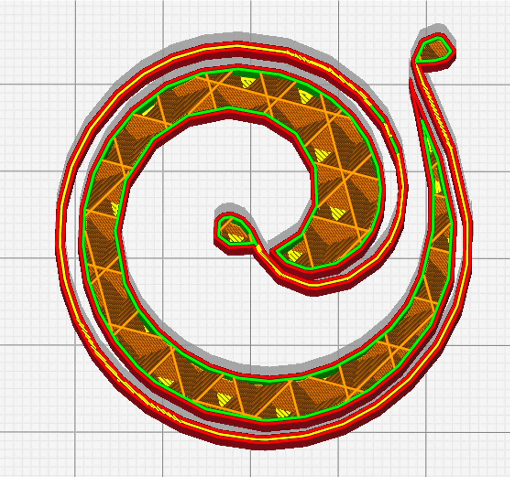 Cubic Infill |
The Cubic fill pattern is a 3D infill pattern of inclined cubes. This infill pattern is recommended for the production of rigid and functional parts that need to withstand multiaxial stresses; such as a shelf bracket, for example. Recommended infill percentages : ±s 50 %. |
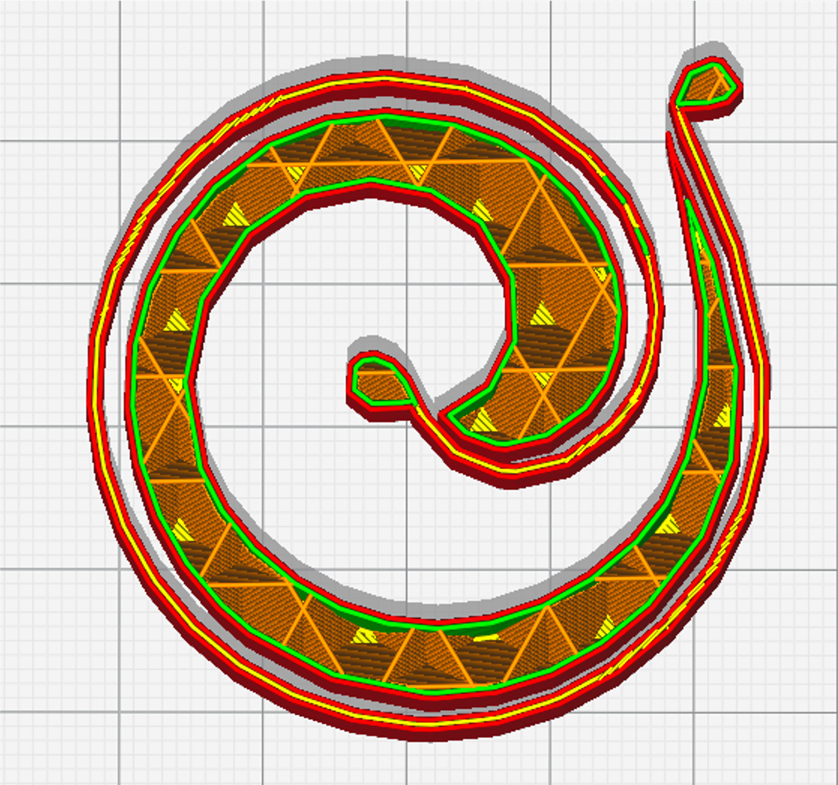
Cubic subdivision Infill |
The Cubic subdivision fill pattern is a 3D infill pattern similar to the Cubic pattern (assembly of inclined cubes). It has the advantage of using less material than the Cubic fill pattern for the same percentage fill. This infill pattern is recommended for the production of rigid and functional parts that need to withstand multiaxial stresses; such as a shelf bracket, for example. Recommended infill percentages : ± 50 %. |
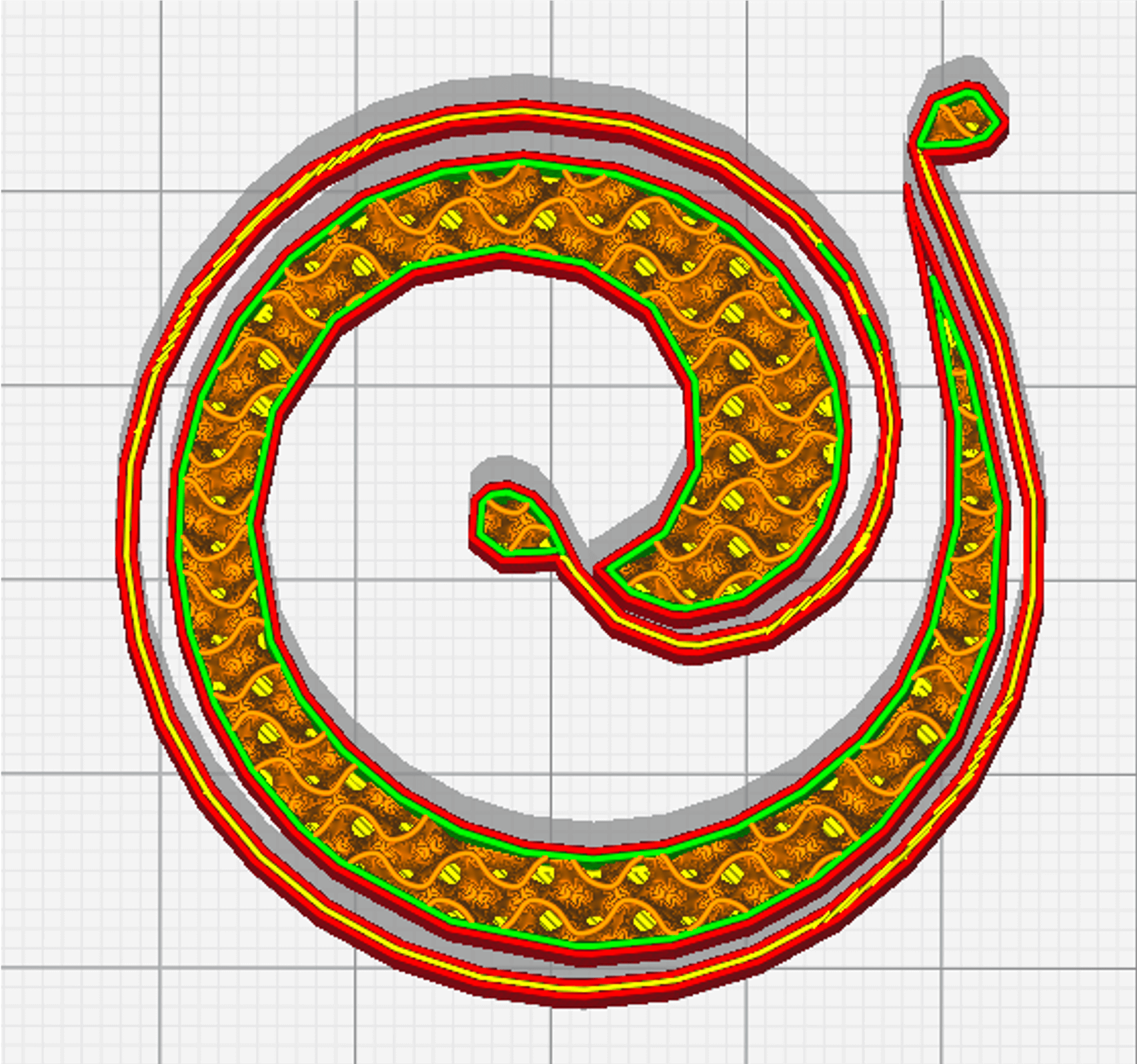 Gyroid Infill |
The Gyroid infill pattern is a particularly unique 3D pattern, it describes a three-dimensional sinusoidal periodic progressive waveform". This infill pattern is recommended for the production of rigid and functional parts that need to withstand multiaxial stresses; such as a shelf bracket, for example. Recommended infill percentages : ± 50 %. |
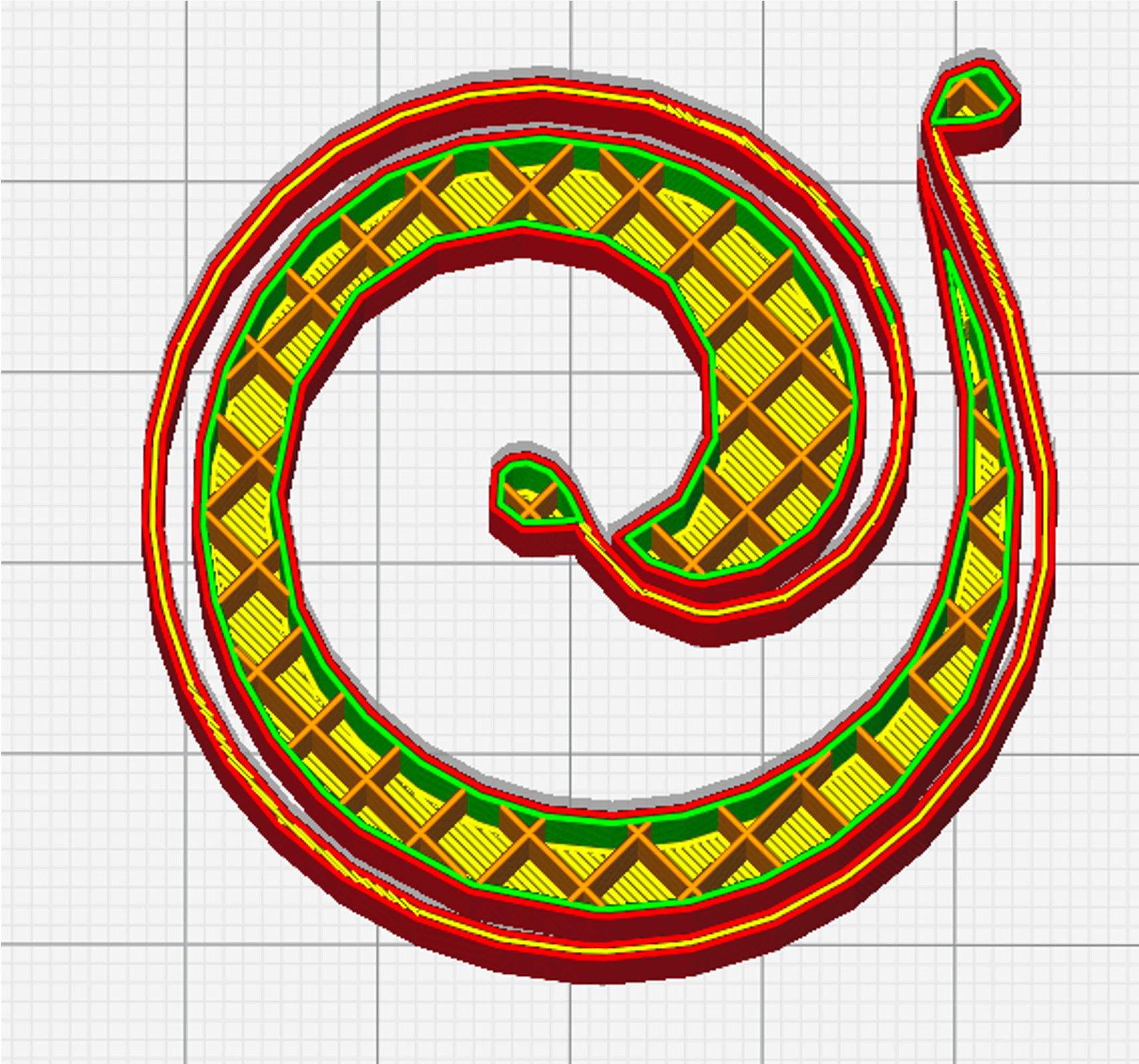 Grid infill |
The Grid infill pattern is an explicit 2D pattern. It describes the production of a grid on a single plane. This pattern can be recommended for the production of parts with low mechanical stress, as can the Triangles and Tri-hexagon infill patterns, which can increase the printing time by up to 25% compared to the Grid. Recommended infill percentages : ± 50 %. |
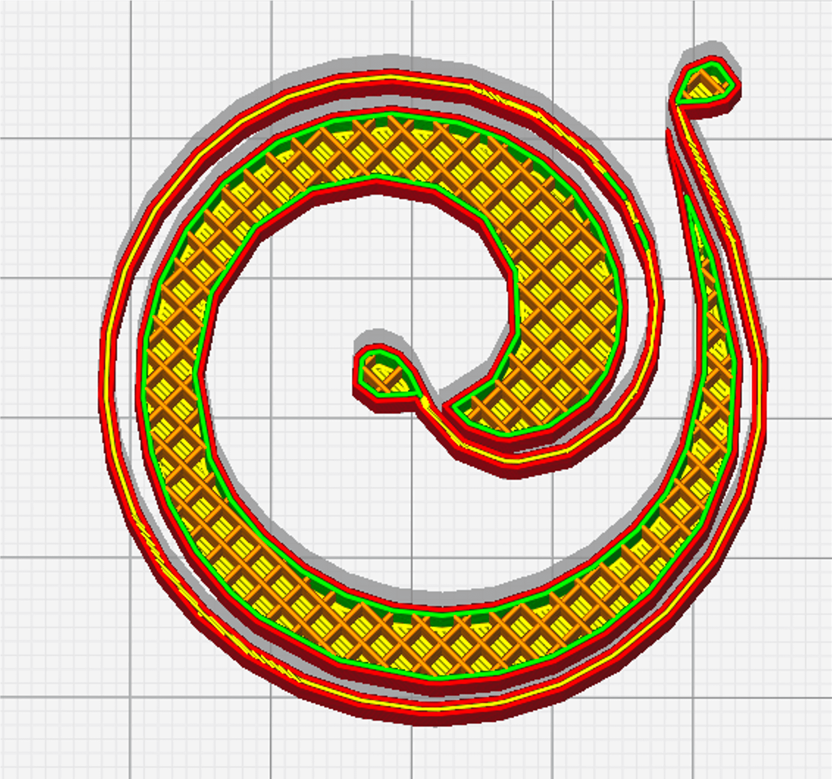 Lines infill |
The Lines infill pattern is a 2D pattern. It describes the production of lines sequentially on the same plane, so the printer will "retract" from one infill line to another. It is possible to vary the infill angle from one layer to another from 0 to 180° with no layer limit. This makes it possible, for example, to create internal structures with specific mechanical properties, impossible with conventional production methods (rebound, mechanical resistance, etc.). This infill pattern is similar to the Zig-Zag pattern. This pattern can be recommended for the production of "fast" parts. Recommended infill percentages : 20 to 100 %. |
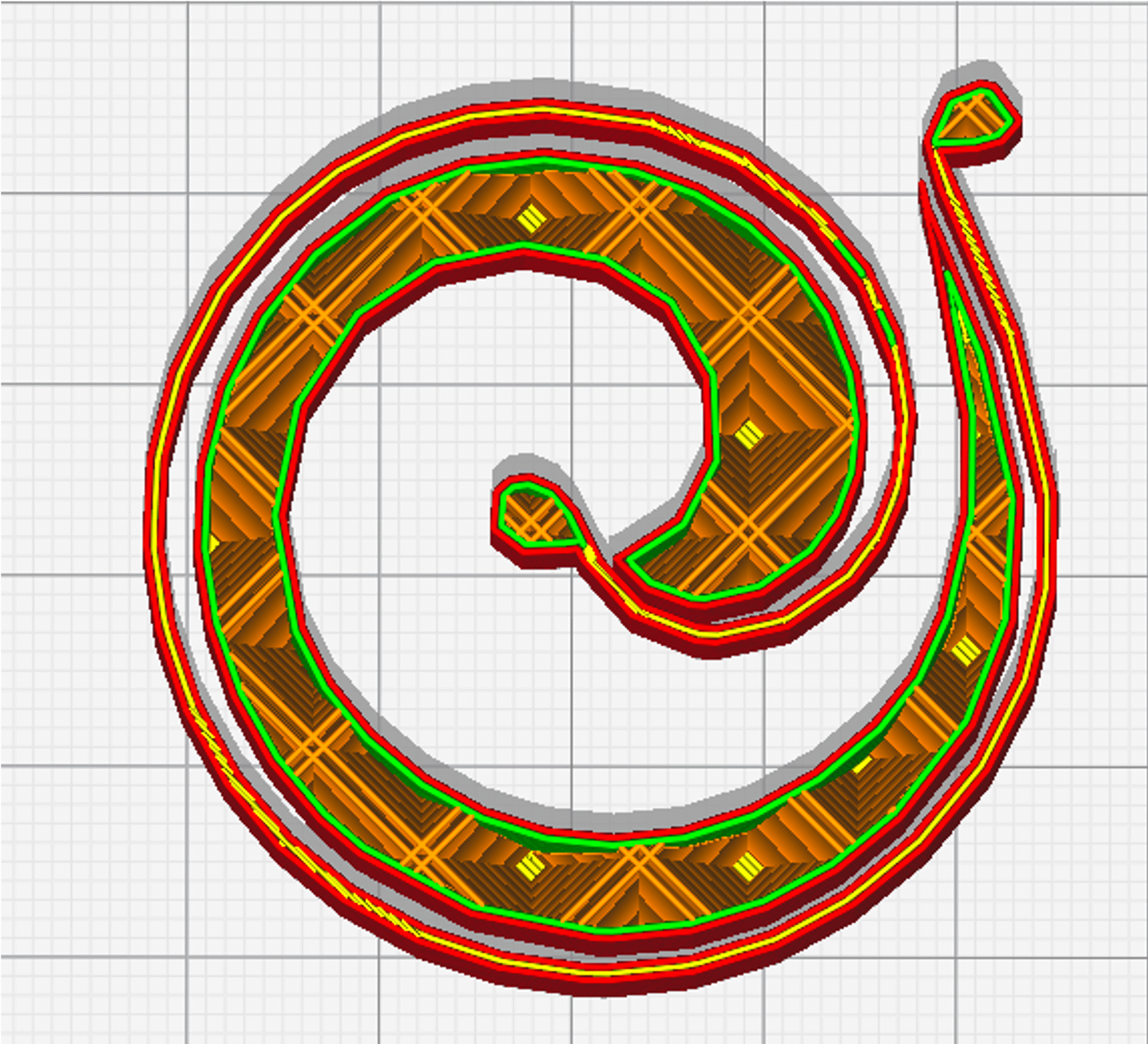 Octet infill |
The Octet infill pattern, also called tetrahedral, is a 3D fill pattern assembling pyramids with a rectangular base. This infill pattern is recommended for the production of rigid and functional parts that need to withstand multiaxial stresses; such as a shelf bracket, for example. Recommended infill percentages : ± 50 %. |
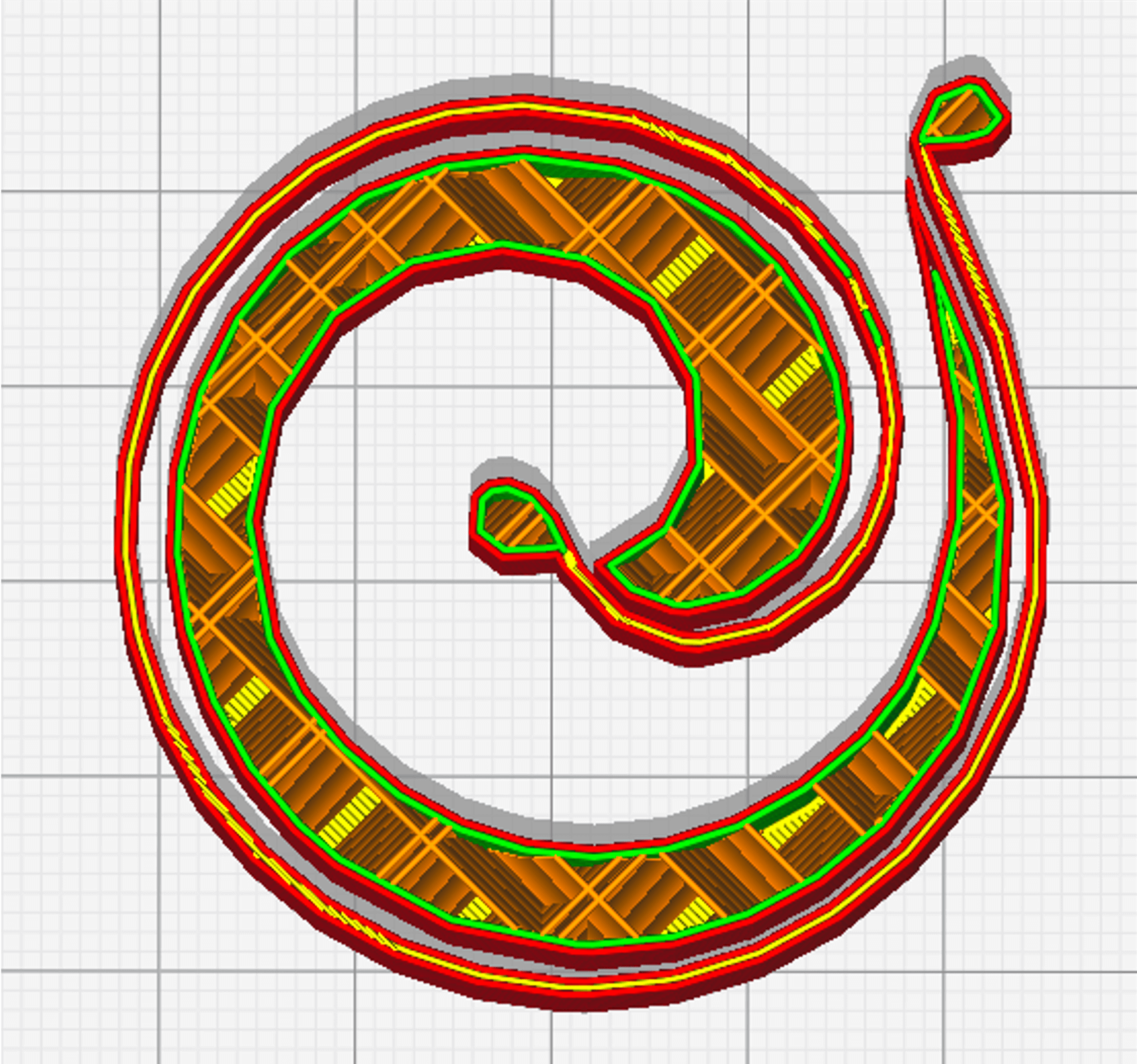 Quarter Cubic Infill |
The Quarter Cubic infill pattern, is a 3D infill pattern assembling pyramids with a rectangular base, 50% of which are offset from each other. The printed part has a complex internal structure. This infill pattern is recommended for the production of rigid and functional parts that need to withstand multiaxial stresses; such as a shelf bracket. Recommended ininfill percentages : ± 50 %. |
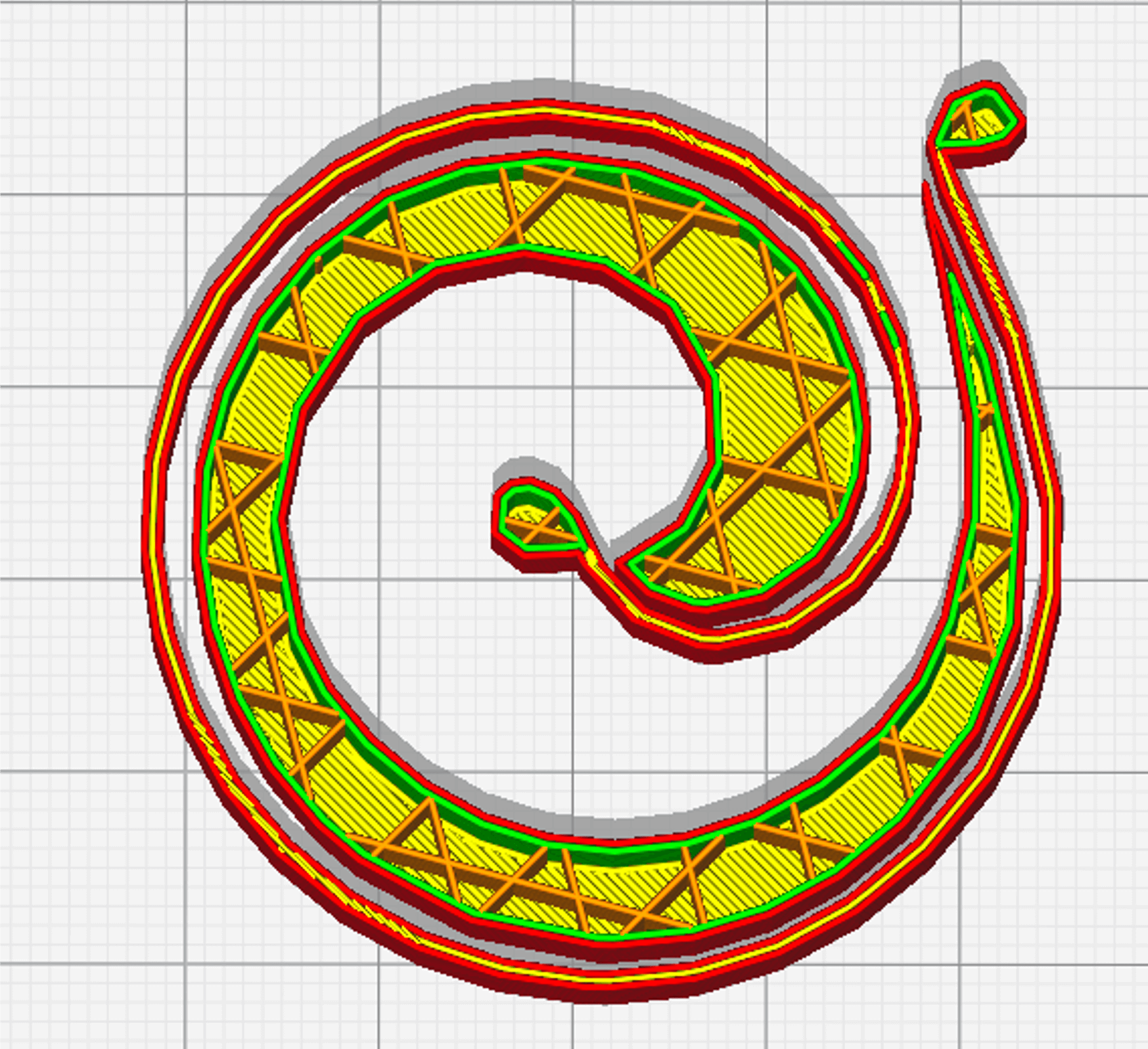 Tri-Hexagon Infill |
The Tri-Hexagon infill pattern is a 2D pattern dedicated to prototyping. Like the Grid and Triangle patterns, it is mainly used for the production of prototypes and / or parts with low mechanical stress. This infill pattern describes the production of hexagons intersected by triangles. The hexagon being an efficient geometry, from a mechanical and material consumption point of view, it seems to allow the production of stronger parts than those integrating a Grid or Triangles infill pattern and this for the same percentage of infill. This pattern can be recommended for the production of parts subject to low mechanical stress, as can the Triangles and Grid infill patterns. Recommended infill percentages : > to 50 %. |
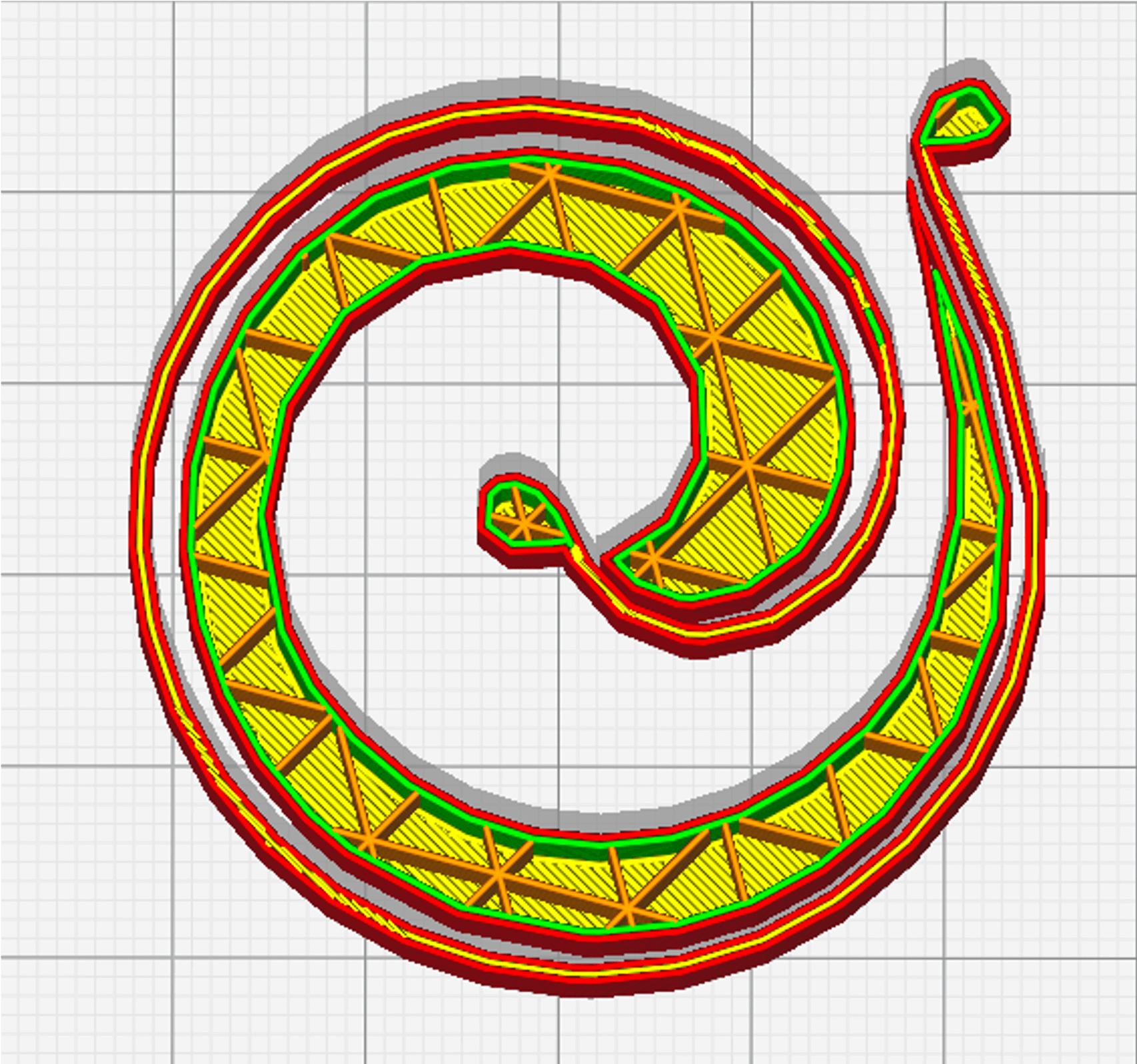
Triangles Infill |
The Triangles infill pattern is a 2D mesh consisting of triangles. This infill pattern has an advantage in terms of mechanical strength when a stress is applied perpendicularly to one side of the printed part. Like the Grid and Tri-Hexagon patterns, it is mainly used for the production of prototypes and/or parts with low mechanical stress. Recommended infill percentages : > to 50 %. |
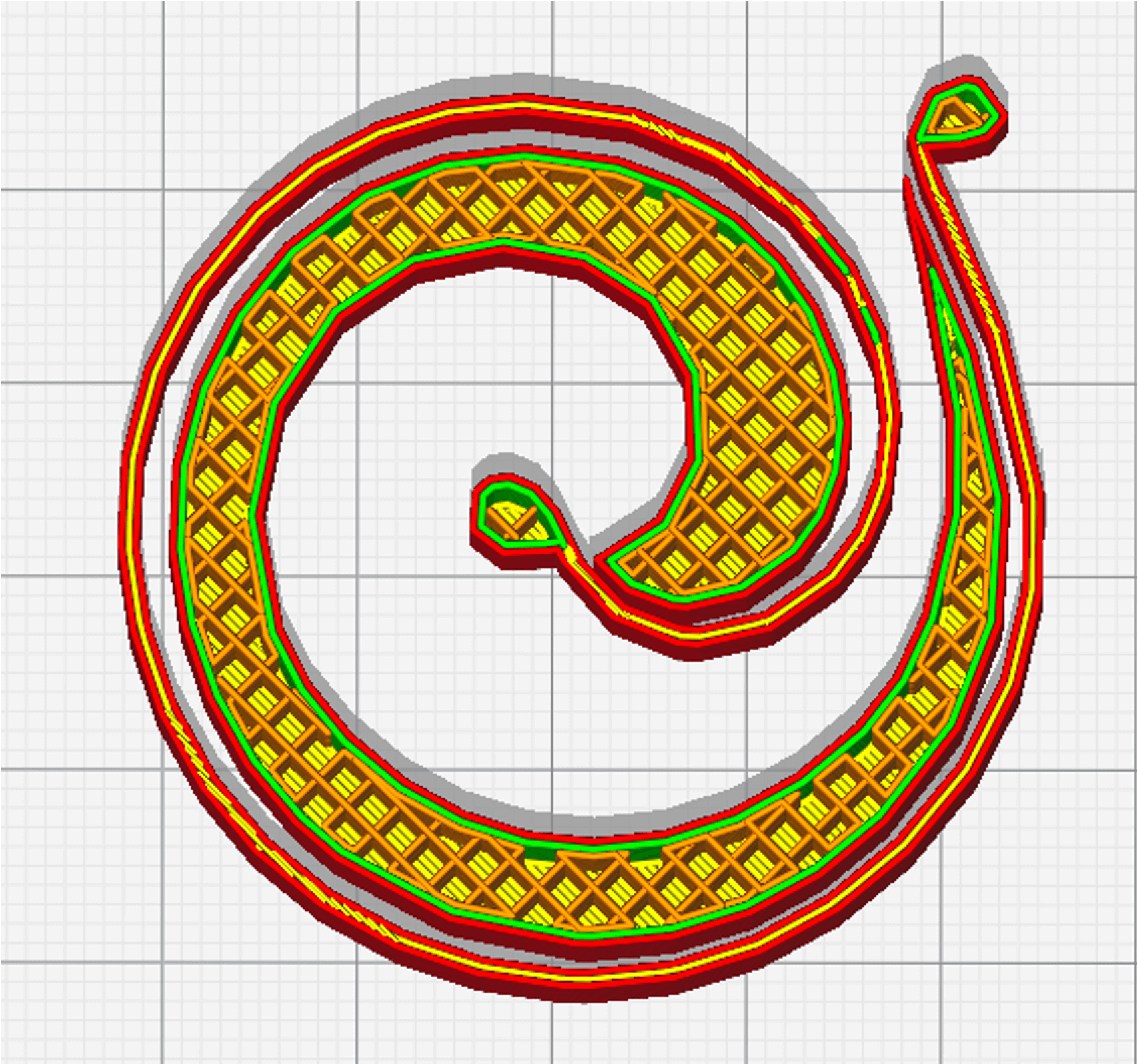 Zig Zag Infill |
The Zig-Zag infill pattern is a 2D pattern. It describes the production of continuous lines on the same plane. It is possible to vary the infill angle from layer to layer from 0 to 180° without layer limitation. This makes it possible, for example, to create internal structures with specific mechanical properties that are impossible with conventional production methods (bounce, mechanical strength, etc.). This infill pattern is similar to the Lines pattern. This pattern can be recommended for the production of "fast" parts. Recommended infill percentages : 20 to 100 %. |
Let’s dive into the possibilities offered by PAM
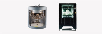
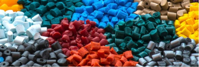
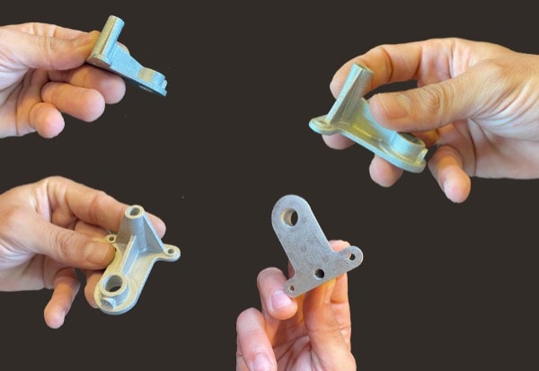
From pellets to object, PAM technology offers the most direct process to high performances end-parts.
Metals Ceramics Commodity Elastomers Performance High Performance.

