First deposited layer
with Pam 3D printers
The last step is the interpretation of the G-Code into a system commands to perform the printing.
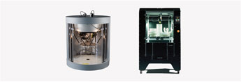
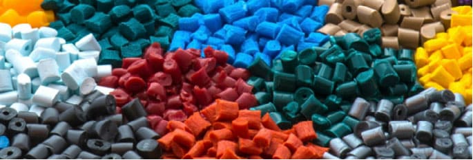
Pam systems operate by successive deposition of melt obtained by direct extrusion of pellets. The first stage of the printing process is the realization of the first layer in immediate contact with the printing build plate.
The challenge of this first layer is to ensure an optimal cohesion with the printing plate in order to offer a robust base for the continuation of the printing process.
This parameter strongly influences the printing strategy and the orientation of the part to be 3D printed. Indeed, to offer the best possible base, the largest possible flat surface of the part is to be preferred.
The first layer is applied to the build plate with a low layer height in order to sufficiently crush the material and thus optimize the adhesion to the printing build plate. Since the first layer deposited is more crushed than the following layers, the printed part may have a slightly flared appearance at its base called "elephant foot".
Elephant Foot is presented in a separated part.
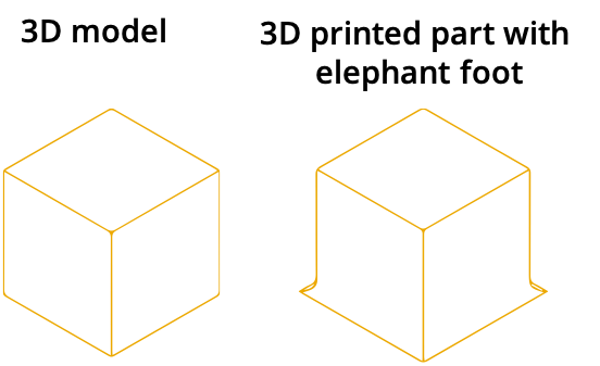
To compensate for this undesirable dimensional effect, it is advisable to provide a slight chamfer at the base of the part.
Another undesirable effect to be taken into account in the printing build plate/part interface is warping of the part due to material shrinkage during cooling.
Warping is presented in a separated part.
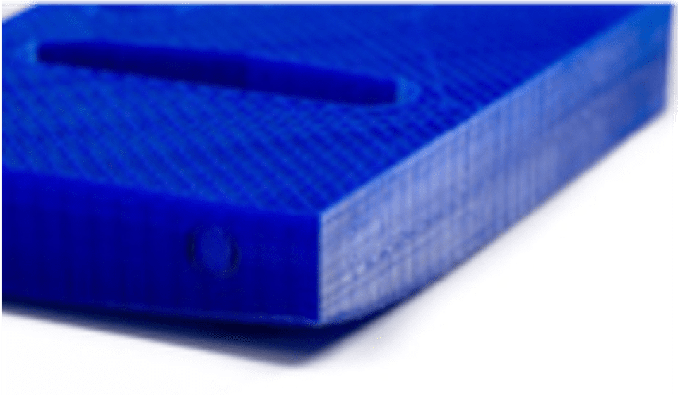
There are several possible solutions to overcome this problem, some are handled during the modelling phases, other during the slicing operations, called helpers.
Helpers
In the preparation of the printout with the part Slicing software, it is also possible to automatically generate structures around the part. For this purpose, brim, skirt and raft structures are available in the software.
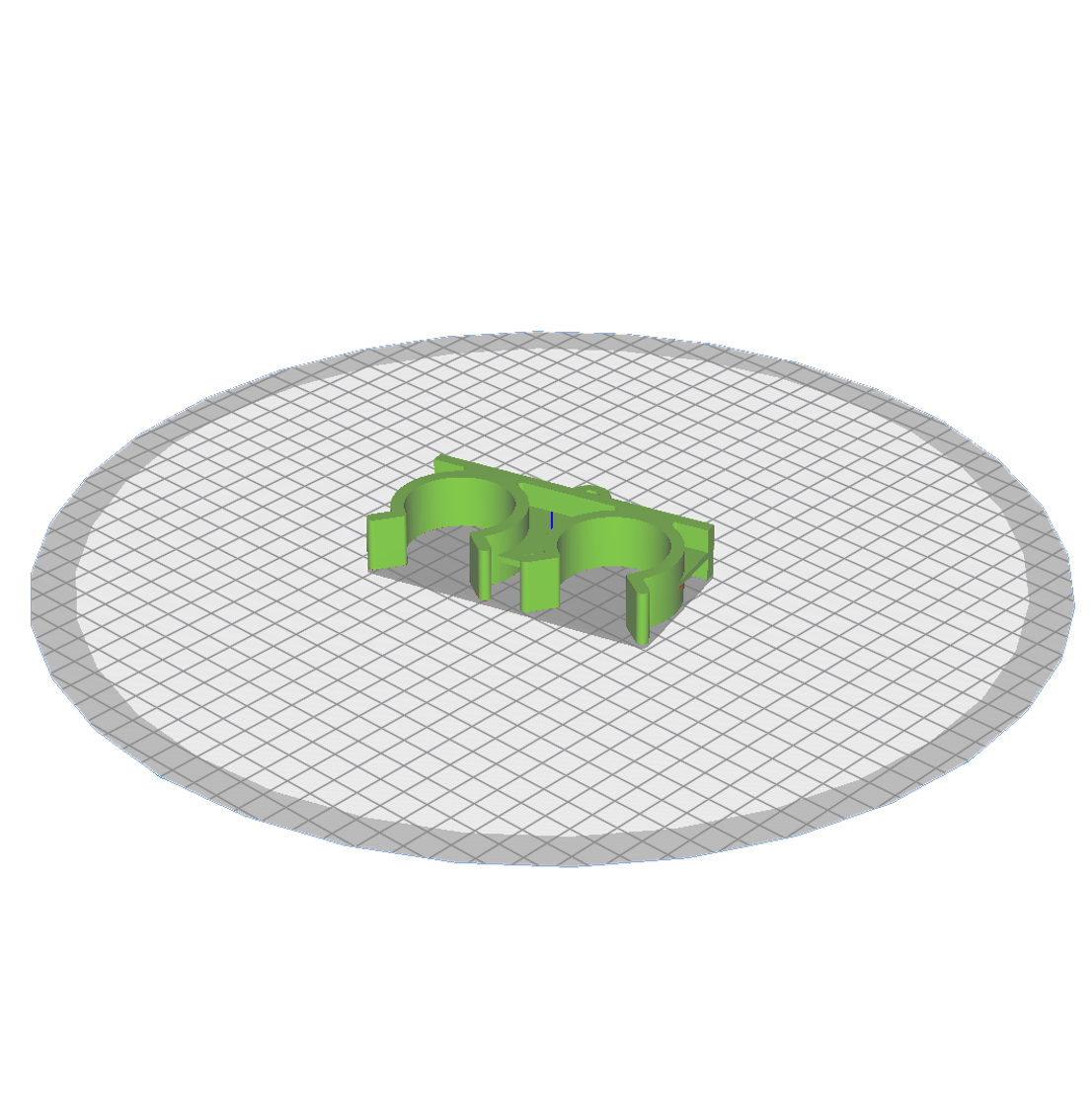
Part presentation with no 3D printing helper.
Axonometric view.
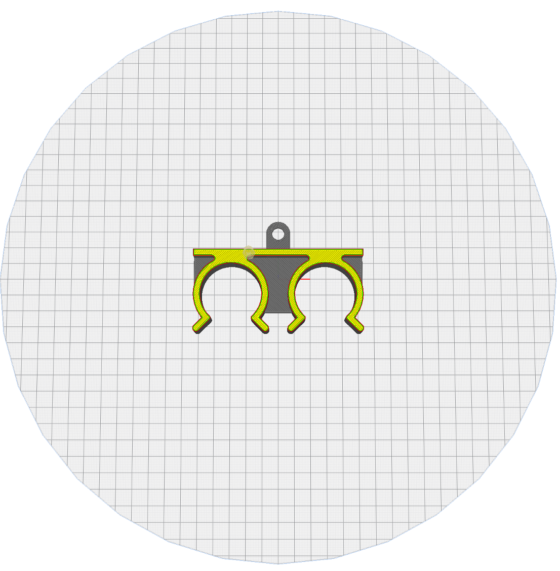
Part presentation with no 3D printing helper.
Top view.
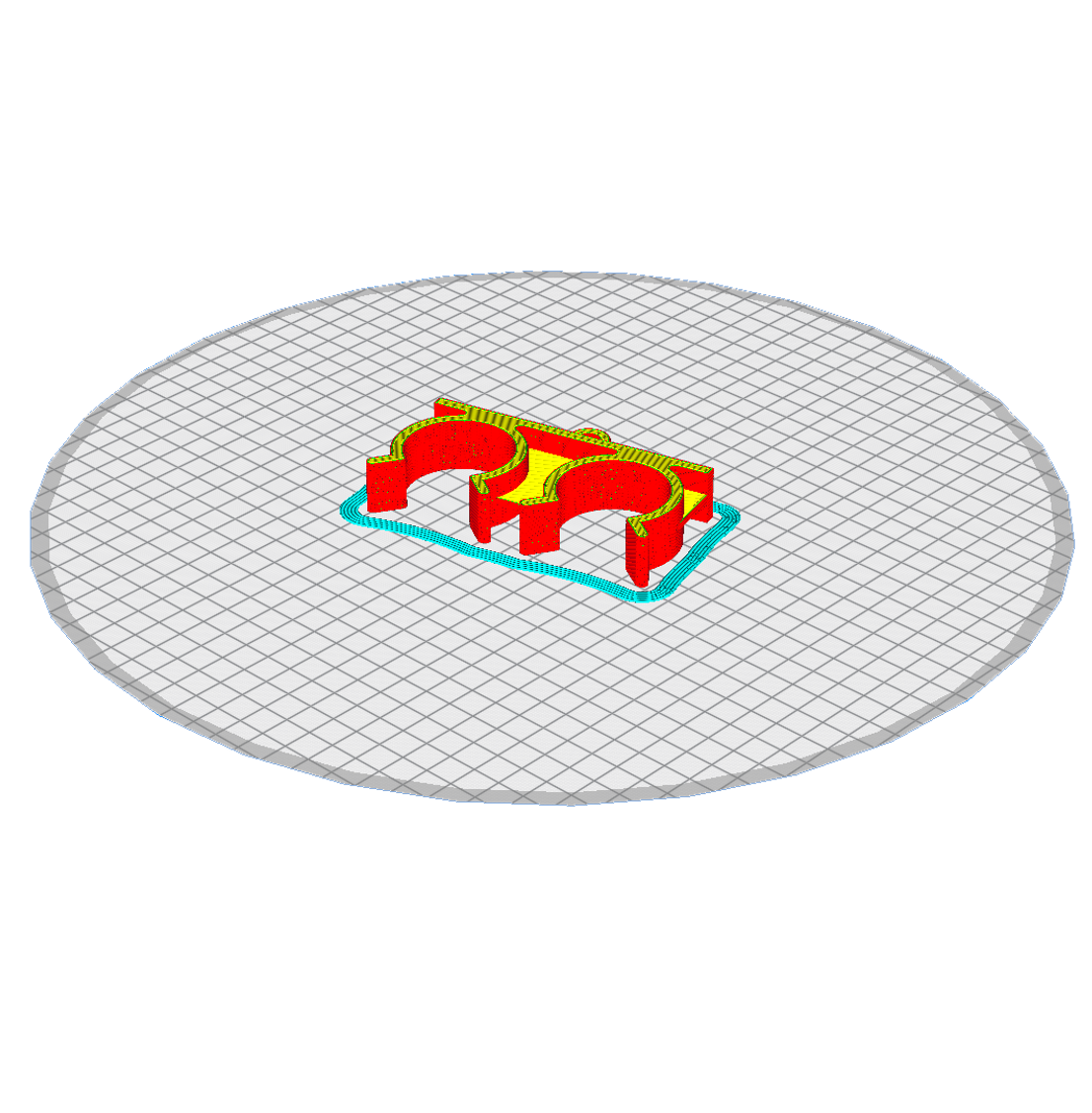
Part presentation with 3D printing helper - Skirt.
Axonometric view.
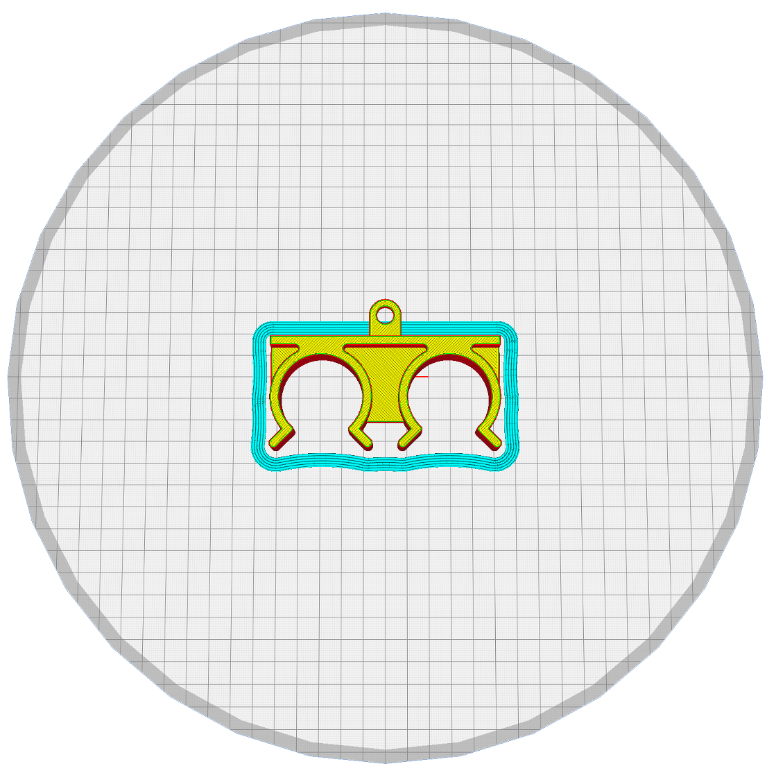
Part presentation with 3D printing helper - Skirt.
Top view.
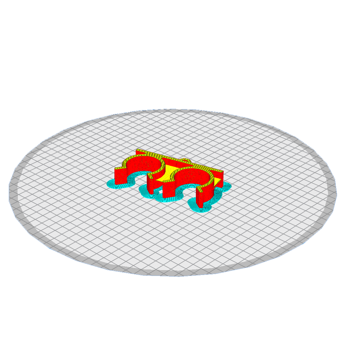
Part presentation with 3D printing helper - Brim.
Axonometric view.
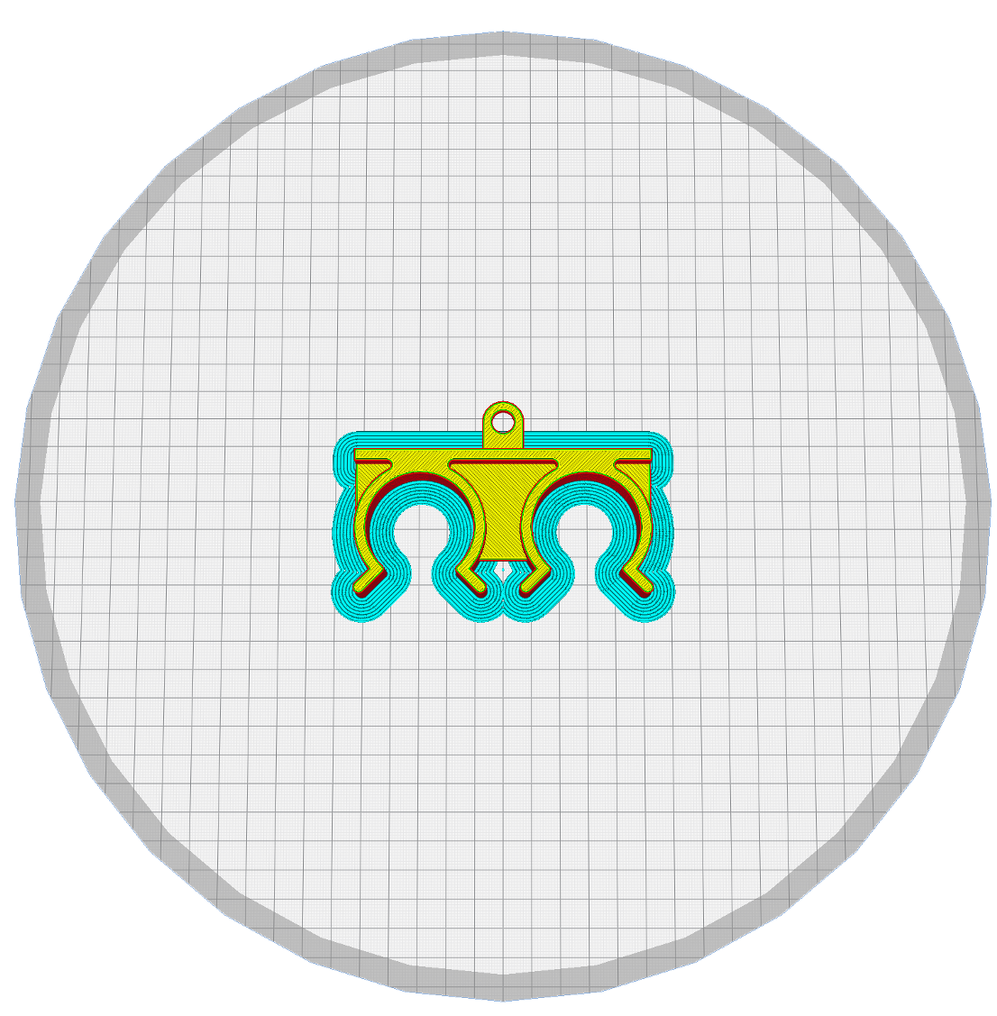
Part presentation with 3D printing helper - Brim.
Top view.
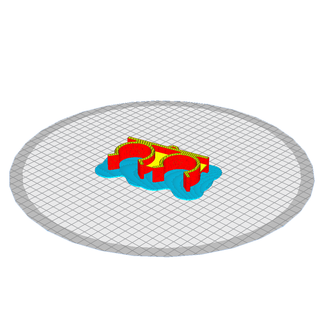
Part presentation with 3D printing helper - Raft.
Axonometric view.
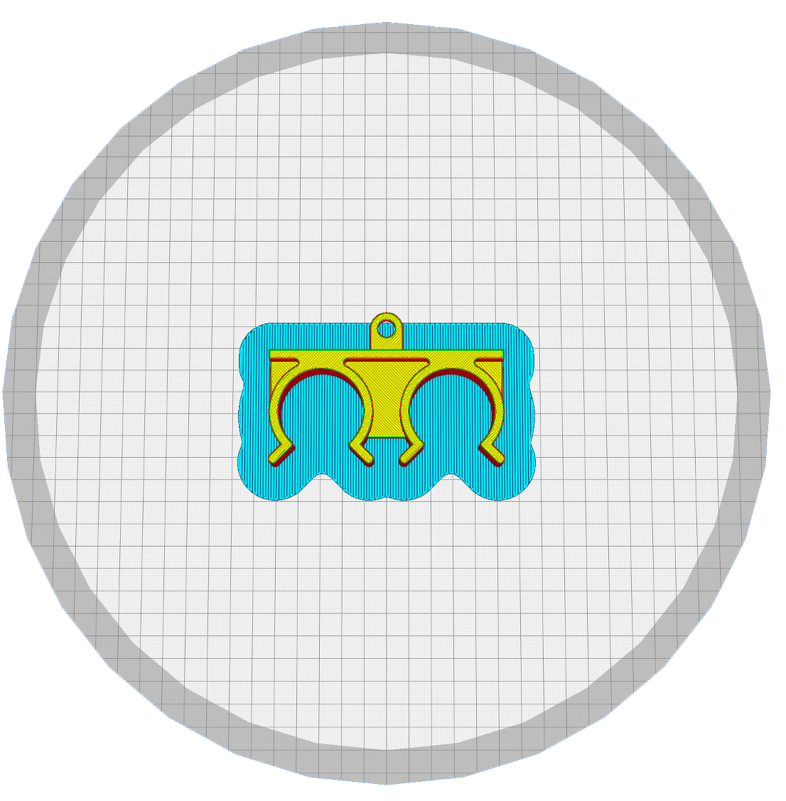
Part presentation with 3D printing helper - Raft.
Top view.
The heating build plate and the radiant disc can be adjusted to mitigate these effects by better control of the cooling of the part.
Finally, specific equipment can be used during printing. The application of an adhesive, glue or lacquer on the build plate ensures better adhesion depending on the material used. It is also possible to choose to print on a micro-perforated tray in order to combine mechanical and chemical adhesion.
Synthesis of the rules for the first deposited layer
| Constraint and elements | Proposed solutions |
Stage of the 3D printing chain | Good practices |
|---|---|---|---|
| Provide a robust print base that maximizes adhesion to the printing build plate. | Choose a print orientation that takes the largest flat surface of the part as the basis for printing. | Slicing. | Position the largest flat surface in contact with the build plate as the printing base. |
| Propose a geometry offering a large flat surface. | Modelling. | Integrate a sufficient flat surface when designing. | |
| Elephant foot effect. | Integrate a chamfer at the base of the part. | Modelling. | |
| Warping / build plate detachment. | Rounding sharp corners. | Modelling. | Avoid sharp corners and draw a fillet corresponding to the diameter of the nozzle to be printed. |
| Add reinforcement elements at the corner. | Modelling. | Plan geometries adapted to the corners of the surface in contact with the table top. | |
| Add a brim, skirt or raft type structure. | Slicing. | ||
| Use and adjust the temperatures of the heating build plate and the temperature radiator. | Slicing & 3D printing process. | When these effects appear, increase the temperature of the tray and use the temperature radiant. | |
| Prepare the printing build plate to optimize the chemical adhesion with the material. | 3D printing process. | .Depending on the printed material, identify the appropriate substrate to prepare the tray for printing. | |
| Use a micro-perforated build plate. | 3D printing process. | In cases where chemical adhesion is insufficient, choose mechanical adhesion. |
Let’s dive into the possibilities offered by PAM
From pellets to object, PAM technology offers the most direct process to high performances end-parts.
Metals Ceramics Commodity Elastomers Performance High Performance.

