Mechanical Testing Protocol
Validate your 3D printing profile.
It is often necessary to characterize the mechanical properties of the printed parts, for that Pollen AM proposes test protocols on standardized specimens.
This part presents the printing protocol that we follow to evaluate the mechanical properties in traction according to the ASTM D638 standard.
We can also adapt this test protocol to your requirements and in accordance with other international standards, such as evaluating compression properties according to ASTM D695, bending properties according to ASTM D790 and shear properties according to ASTM D5379.
Tensile test specimen
The ADSTM D638 standard provides a framework for the testing protocol evaluating the tensile properties of plastics. It is used to measure the mechanical tensile properties of plastics, including tensile strength, yield strength, elongation and Poisson's ratio.
The test specimens have a dumbbell shape with a reduced cross-section, the area in which failure will occur during the test.
The samples are tested under specific environmental conditions (temperature, humidity) and experimental parameters (test speed, etc.).
ASTM D638 can be used to test materials up to 14 mm thick.
Thin films and sheets (less than 1.0 mm thick), should be tested according to ASTM D882.
Tensile mechanical properties of plastics - typical experimental parameters
Number of samples: 5 minimum per printing direction.
Note: It is recommended to test multiple print orientations (X, Y, Z45 and Z) to quantify the major print orientations. In addition, it is common to vary the orientation and filling parameters which will also influence the mechanical properties of the parts.
Crosshead speed: from 5 mm/min to 500 mm/min; it varies according to the material rigidity, shape and thickness.
As a general rule, the softer the material, the faster it will be stretched.
Temperature of the conditioning and the test: generally 23 ± 2 ° C.
Relative humidity of conditioning and testing: 50 ± 5%.
Specimen size: Specimen size is adjusted according to the thickness of the material.
Tensile specimen Type I, II, III and V
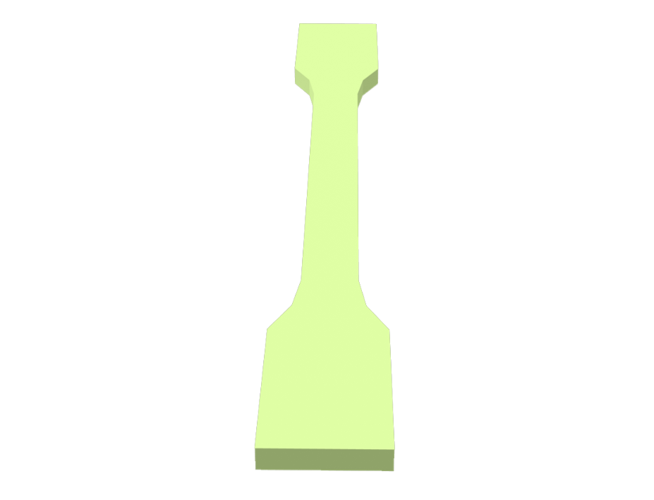
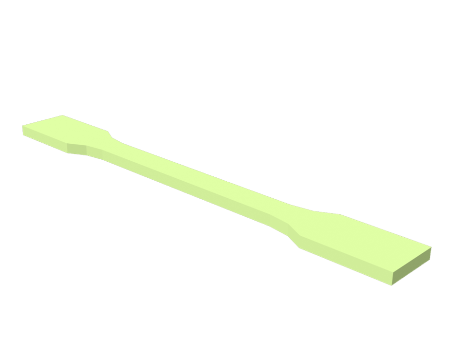
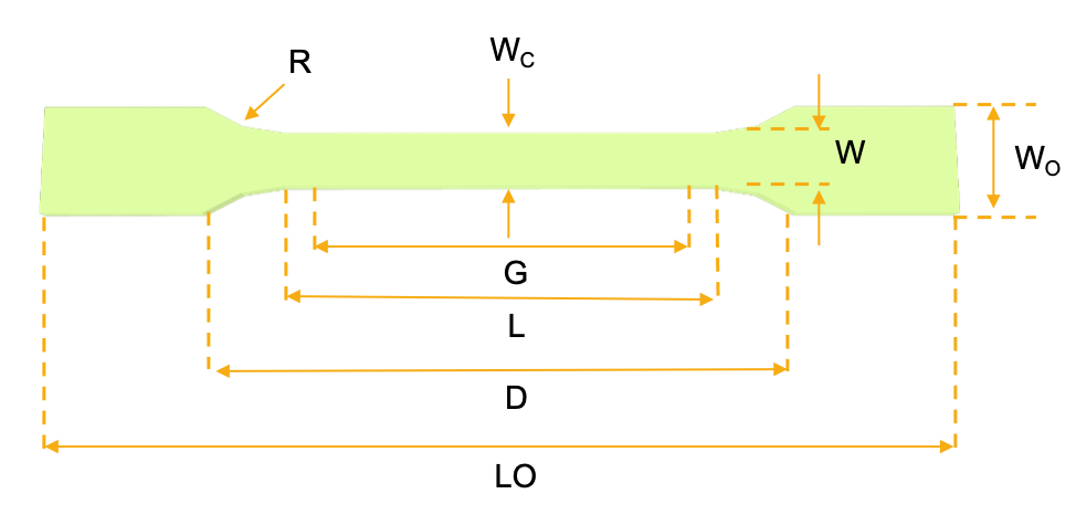

Tensile specimen Type IV


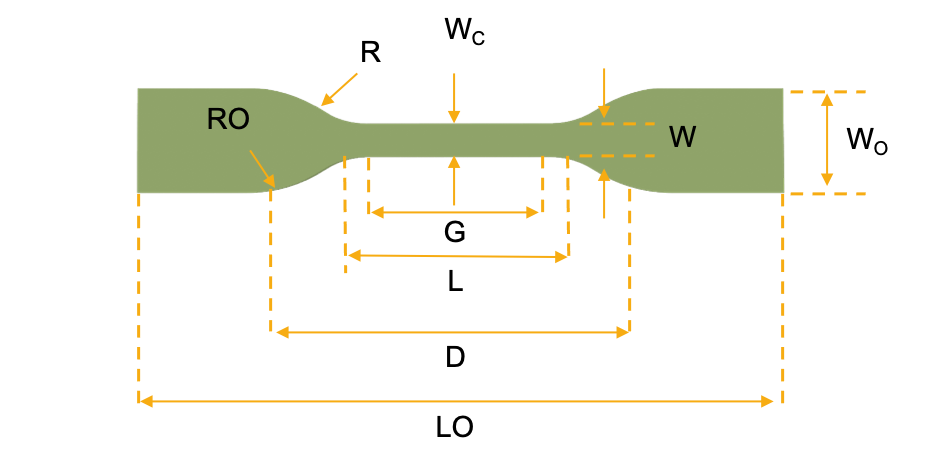

Download the Type I tensile specimen
Download the Type IV tensile specimen
Specimen Dimensions for Thickness, T, mm (in.)A
| Dimensions (see drawings) |
7 (0.28) or under |
Over 7 to 14 (0.28 to 0.55), incl |
4 (0.16) or under |
Tolerances | ||
|---|---|---|---|---|---|---|
| Type I |
Type II |
Type III |
Type IVB |
Type VC, D |
||
| W Width of narrow sectionE, F |
13 (0.50) |
6 (0.25) |
19 (0.75) |
6 (0.25) |
3.18 (0.125) |
±0.5 (±0.02)B, C |
| L Length of narrow section |
57 (2.25) |
57 (2.25) |
57 (2.25) |
33 (1.30) |
9.53 (0.375) |
±0.5 (±0.02)C |
| WO Width overall, minG |
19 (0.75) |
19 (0.75) |
29 (1.13) |
19 (0.75) |
+ 6.4 (+ 0.25) |
|
| WO Width overall, minG |
9.53 (0.375) |
+ 3.18 (+ 0.125) |
||||
| LO Length overall, minH |
165 (6.5) |
183 (7.2) |
246 (9.7) |
115 (4.5) |
63.5 (2.5) |
no max (no max) |
| G Gage lengthI |
50 (2.00) |
50 (2.00) |
50 (2.00) |
7.62 (0.300) |
±0.25 (±0.010)C |
|
| G Gage lengthI |
25 (1.00) |
±0.13 (±0.005) |
||||
| D
Distance between grips |
115 (4.5) |
135 (5.3) |
115 (4.5) |
65 (2.5)J |
25.4 (1.0) |
±5 (±0.2) |
| R Radius of fillet |
76 (3.00) |
76 (3.00) |
76 (3.00) |
14 (0.56) |
12.7 (0.5) |
±1 (±0.04)C |
| RO Outer radius (Type IV) |
25 (1.00) |
±1 (±0.04) |
||||
A Thickness, T, shall be 3.2± 0.4 mm (0.13 ± 0.02 in.) for all types of molded specimens, and for other Types I and II specimens where possible. If specimens are machined from sheets or plates, thickness, T, shall be the thickness of the sheet or plate provided this does not exceed the range stated for the intended specimen type. For sheets of nominal thickness greater than 14 mm (0.55 in.) the specimens shall be machined to 14 ± 0.4 mm (0.55 ± 0.02 in.) in thickness, for use with the Type III specimen. For sheets of nominal thickness between 14 and 51 mm (0.55 and 2 in.) approximately equal amounts shall be machined from each surface. For thicker sheets both surfaces of the specimen shall be machined, and the location of the specimen with reference to the original thickness of the sheet shall be noted. Tolerances on thickness less than 14 mm (0.55 in.) shall be those standard for the grade of material tested.
B For the Type IV specimen, the internal width of the narrow section of the die shall be 6.00 ± 0.05 mm (0.250 ± 0.002 in.). The dimensions are essentially those of Die C in Test Methods D412.
C The Type V specimen shall be machined or die cut to the dimensions shown, or molded in a mold whose cavity has these dimensions. The dimensions shall be:
W = 3.18 ± 0.03 mm (0.125 ± 0.001 in.),
L = 9.53 ± 0.08 mm (0.375 ± 0.003 in.),
G = 7.62 ± 0.02 mm (0.300 ± 0.001 in.),
R = 12.7 ± 0.08 mm (0.500 ± 0.003 in.).
The other tolerances are those in the table.
D Supporting data on the introduction of the L specimen of Test Method D1822 as the Type V specimen are available from ASTM Headquarters. Request RR:D20-1038. EThe tolerances of the width at the center Wc shall be +0.00 mm, −0.10 mm ( +0.000 in., −0.004 in.) compared with width W at other parts of the reduced section. Any reduction in W at the center shall be gradual, equally on each side so that no abrupt changes in dimension result.
F For molded specimens, a draft of not over 0.13 mm (0.005 in.) is allowed for either Type I or II specimens 3.2 mm (0.13 in.) in thickness. See diagram below and this shall be taken into account when calculating width of the specimen. Thus a typical section of a molded Type I specimen, having the maximum allowable draft, could be as follows:
G Overall widths greater than the minimum indicated are used for some materials in order to avoid breaking in the grips.
H Overall lengths greater than the minimum indicated are used for some materials to avoid breaking in the grips or to satisfy special test requirements.
I Test marks or initial extensometer span.
J When self-tightening grips are used, for highly extensible polymers, the distance between grips will depend upon the types of grips used and may not be critical if maintained uniform once chosen.
Let’s dive into the possibilities offered by PAM
From pellets to object, PAM technology offers the most direct process to high performances end-parts.
Metals Ceramics Commodity Elastomers Performance High Performance.

